

In the past, fixtures equipped with traditional bulbs were exclusively dimmed using either TRIAC or transistor dimmers. With the advent of LED bulbs, dimming was only possible in dimmable versions, and solely through on-edge transistor dimming.
Currently, all fixtures are outfitted with LED modules (or LED strips) powered by a ballast (driver). Using the conventional method (in the power supply), it is practically impossible to dim the lights. If attempted, you will find that regulation does not function properly, leading to flickering and the light turning off when voltage is reduced.
Hence, most ballasts come with an interface that facilitates dimming in two ways:
1) External voltage 0-10V (or 1-10V)
2) Using the DALI protocol
Dimming is achieved using an external 0-10V voltage source, where 10V equals 100% brightness and 0V equals 0% brightness. Alternatively, a 1-10V option is available, in which case it is necessary to ensure the complete shutdown of the entire ballast (via relay) because at 1%, the light still emits minimal brightness.
This method enables group dimming, meaning the control of multiple ballasts simultaneously by parallel connecting the control inputs of 0-10V.
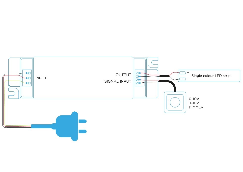
Some ballasts come equipped with a built-in 10V source, allowing for dimming using only a potentiometer (voltage divider).
However, it comes with some drawbacks:
- a) All lights are regulated uniformly.
- b) The maximum cable length for control is 10 meters.
- c) Voltage drop occurs at the end of the cable, leading to varying brightness.
- d) The number of regulated ballasts must match the maximum current load of the 0-10V output, usually around XXX mA, capable of controlling a maximum of X ballasts.
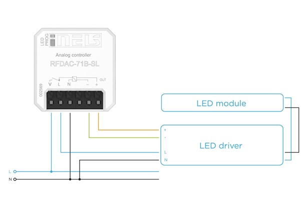
iNELS Wireless offers a solution for this dimming method with the RFDAC-71B unit, which includes a relay for complete ballast shutdown. This ensures that no current passes through the fixture even when dimmed to the minimum.
DALI Dimming
DALI is a 2-wire addressable bus system where each ballast has its own address.
Learn more: Digital Addressable Lighting Interface
The control unit (DALI master, DALI dimmer, etc.) enables independent dimming of each address.

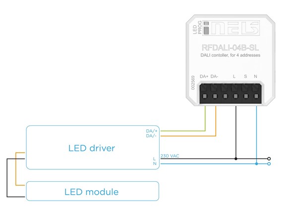
Schema of connection for the control unit RFDALI for 1 light:
DALI masters are available in configurations of 64/128/256 addresses, while DALI dimmers allow dimming of a single address.
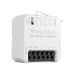
The wireless DALI dimmer RFDALI-04B-SL supports dimming for 4 addresses, and RFDALI-32B-SL accommodates 32 addresses.
Real connection of the unit into the suspended ceiling:
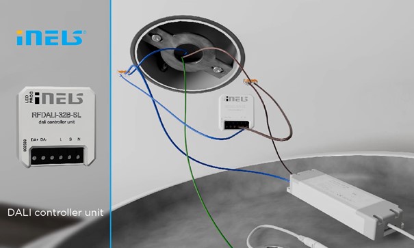
The single RFDALI unit can control 1 or more ballasts on a single DALI bus simultaneously, up to a maximum of 32.
Wiring diagram for 4 luminaires:

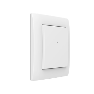
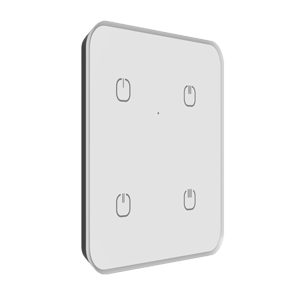
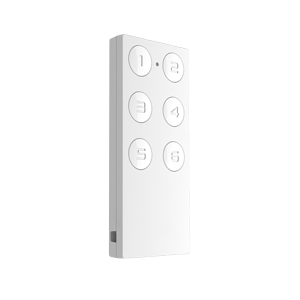
If we want to control 1 or all lights on the DALI bus as a single lighting zone, it is sufficient to connect the RFDALI unit to this bus. The RFDALI unit provides power to the DALI bus and automatically loads all units found on the bus using the Broadcast mode. These lights can then be controlled as a single group by connecting a button to terminal S or by pairing any wireless controller (switches, key fobs, wireless transmitters, etc.).
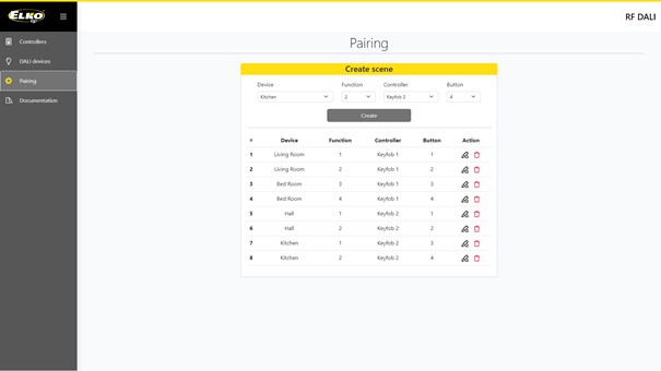
If we want to control each light on the bus separately, we can pair DALI addresses to different wireless controllers individually. These settings are done in the web interface provided by RFDALI, allowing the user to assign any number of addresses to any number of controllers and additionally specify the function that the controller will perform when activated on the selected group of lights. Whether it’s simply turning on/off, dimming the unit, or activating features like sunset simulation depends entirely on the user’s needs.